This is based on the excellent series by SDG Electronics on YouTube.
MOSFET calculations
Here are Steve's calculations, for his setup. He explains these further in his video.

Towards the bottom, notice he calculates the percentage of time spent by the MOSFET in switching (wasting power), so I worked this out as well:

If you're wondering how to the Gate charge value is converted to time (in seconds), just remember that Ampere stands for "Coulomb per second" or
C/s. I've expanded on the algebra to perform the conversion.
MOSFET Power Requirements
The datasheet details
Rds(on), which is the resistance of the MOSFET when on; this is actually specified by a chart as this varied depending on Id (drain current).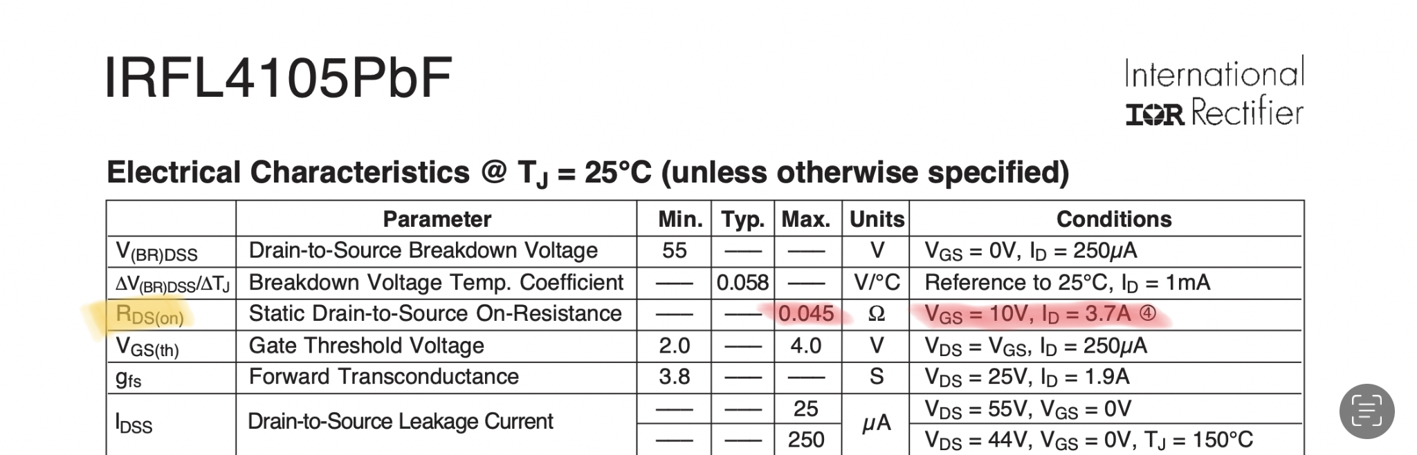
My particular requirements are slightly different to Steve's. My CC LED Driver is a 120mA version (Steve is using a 150mA version). Taking my MOSFET's Rds(on) as 45mA shows that it will only dissipate ~405mW, which is more efficient than Steve's case.
I also plan to use large ground-planes around the MOSFETs to further aid as a thermal mass.

Schematic
Since I'm using EAGLE, I ended up searching for identical or similar parts on Farnell UK, as I import through a supplier.
Here's the MOSFET side - notice that I've added the option to install a gate drive resistor. Steve talks about this further in this video and provides details on an app note that goes into depth about ringing and how to potentially counteract this.
In my version, I've opted to use schottky diodes.

Level shifting logic and gate driver. This is identical to the configuration used by Steve.

Here's the microcontroller interfacing header

Status indicators, using regular LEDs. Steve suggested to go with GaN LEDs but I couldn't find too many on Farnell
