Dear reader, please be warned as I'm about to take you on a journey that one really shouldn't have to embark on. The premise is simple, I want to send and read some data via UART (or commonly known as RS232/Serial comms).
This is pretty much your Embedded 101 task, and back in my day at University, this was something I'd bit-bang on a PIC mcu or rely on a hardware USART peripheral to get the job done. I wanted to do the same thing, in bare-metal Rust + Embassy.
Should be easy right?
Well, in all fairness, it takes about 2-3 minutes to download a simple Arduino "sketch" to do the same thing, and the code is quite succinct.
/*
 * Serial echo for the Arduino Portenta H7
 *
 * This is a simple example, and can be cleaned up a lot more.
 *
 * Copyright (c) 2024 Michael de Silva <michael@mwdesilva.com>
 */

#ifdef CORE_CM7

UART myUART3(PJ_8,  PJ_9,  NC, NC);

// (char)"A";
int i = 65;

void setup() {
  pinMode(LEDB, OUTPUT);                // LEDB = blue
                                        // LEDG or LED_BUILTIN = green
                                        // LEDR = red

  Serial.begin(115200);

  myUART3.begin(115200);
  myUART3.setTimeout(10);
}

void loop() {
  if (i > 90){
    i = 65;
  }                                     // ascii 65 =  letter A,   ascii 90 = letter Z

  myUART3.write((char)i++);             // ascii code for numbers A to Z

  int x = 0;
  if (myUART3.available()) {
    // Toggle Blue LED
    digitalWrite(LEDB, !digitalRead(LEDB));

    do {                                // Read all to clear buffer
      x++;
      Serial.write(myUART3.read());     // Read it and send it out Serial (USB)
    } while (myUART3.available());

    Serial.print("Chars: ");
    Serial.print(x);
    Serial.write("\r\n");
  }

  delay(500);
}

#endif
New comers to this space might wonder, why bother with the pain of bare-metal Rust, and well, there's two sides to it. The pain is way less once you understand what you're doing, and how to go about it. That said, there is a higher barrier to success in most cases. If you're new to Embedded and Arduino in general, go grab that blinky sketch. In stead of looping and blinking an LED for ever, just do a single loop iteration where you change the GPIO output from LOW to HIGH and back to LOW again (keeping the same pulse-width). Using a logic analyser (like Saleae) or an Oscilloscope, measure the time between each state transition. It'll be surprising and possibly in the milli-second range (even with a high clock speed MCU). In any case, there is an impactful delay in doing small simple things in the ArduinoCore-mbed stack. This is one of the reasons that makes bare-metal Rust so attractive.
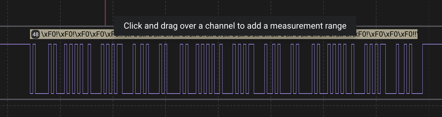
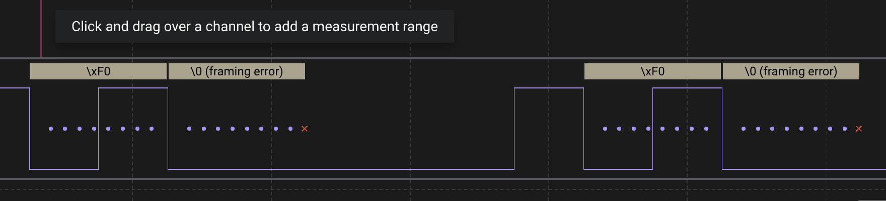
Right, back to the main show. So where did things go wrong for me exactly? Well, I started to work off the Embassy examples for async USART with DMA but ran into an error that is still pending.
I decided to take a step back and try blocking UART, the simplest possible "Hello world" in the UART space. This is where things broke down for me quickly.
Blocking Tx just wouldn't work.
To make things more weird, if I changed the STM32h747xi's sys clock from 480MHz to 19.2MHz with my
stm32h747_slow power config, the Tx "garbage" would look different. Still broken, but different. Yeah.#[cfg(feature = "stm32h747_slow")]
{
config.rcc.pll1 = Some(Pll {
source: PllSource::HSI,
prediv: PllPreDiv::DIV8,
mul: PllMul::MUL120,
divp: Some(PllDiv::DIV50), // ((64/8)*120)/50 = 19.2MHz
divq: Some(PllDiv::DIV80), // ((64/8)*120)/8 = 12MHz / SPI1 cksel defaults to pll1_q
divr: None,
});
config.rcc.pll2 = Some(Pll {
source: PllSource::HSI,
prediv: PllPreDiv::DIV8,
mul: PllMul::MUL50,
divp: Some(PllDiv::DIV4), // ((64/8)*50)/4 = 100MHz
divq: None,
divr: None,
});
}The Tx would look like
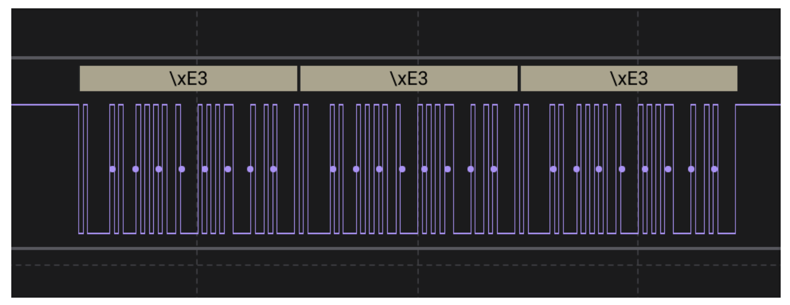
Using the
stm32h747_480 power config at baud 115,200 would make this look like#[cfg(feature = "stm32h747_480")]
{
config.rcc.pll1 = Some(Pll {
source: PllSource::HSI,
prediv: PllPreDiv::DIV8,
mul: PllMul::MUL120,
divp: Some(PllDiv::DIV2), // ((64/8)*120)/2 = 480MHz
divq: Some(PllDiv::DIV8), // ((64/8)*120)/8 = 120MHz / SPI1 cksel defaults to pll1_q
divr: None,
});
config.rcc.pll2 = Some(Pll {
source: PllSource::HSI,
prediv: PllPreDiv::DIV8,
mul: PllMul::MUL50,
divp: Some(PllDiv::DIV4), // ((64/8)*50)/4 = 100MHz
divq: None,
divr: None,
});
}
This weird sequence was a head scratcher for sure. But in hindsight, I may have been doing something seriously wrong.
Using STM32CubeIDE to get a baseline
This was a good idea, and I used a spare Nucleo board first and the Portenta H7 with the Segger J-Link mini to get a baseline UART config, and finally write some clean serial data from the Portenta H7 - without the Arduino Mbed stack!
For this test, I wired up an Arduino Uno R2 WiFI which is based on an ATmel ATMega mcu. One thing is for sure, flashing this is SUPER quick. I loaded it up with a sketch to do a simple UART echo
#ifndef outputSerial
#define outputSerial Serial1
#endif

int incomingByte = 0;               // For incoming serial data

void setup() {
    outputSerial.begin(115200);     // Opens serial port, sets data rate to 115200 bps

    pinMode(LED_BUILTIN, OUTPUT);   // Green
}

void toggle_pin(pin_size_t *pin) {
  digitalWrite(*pin, LOW);
  delay(100);
  digitalWrite(*pin, HIGH);
  delay(100);
}

void toggle_led_builtin() {
  digitalWrite(LED_BUILTIN, LOW);
  delay(100);
  digitalWrite(LED_BUILTIN, HIGH);
  delay(100);
}

void loop() {
  // send data only when you receive data:
  if (outputSerial.available() > 0) {
    toggle_led_builtin();

    // read the incoming byte:
    incomingByte = outputSerial.read();

    outputSerial.print("Got: ");
    // say what you got:
    outputSerial.print((char)incomingByte);
    outputSerial.println("");
  }
  else {
    toggle_led_builtin();
  }

  delay(100);
}
I was able to use
screen to verify the Uno worked like it should.Going a bit deeper...
It was time to start looking through the docs to figure out where I'm going wrong, and of course through the HAL too. Could this be a
H7xx family power config related issue that many are still concerned about? See my comments on this issue and also James Munns has updated the Embassy FAQ about this too.Let's first see how the UART is initialised
impl<'d, T: BasicInstance> Uart<'d, T, Blocking> {
    /// Create a new blocking bidirectional UART.
    pub fn new_blocking(
        peri: impl Peripheral<P = T> + 'd,
        rx: impl Peripheral<P = impl RxPin<T>> + 'd,
        tx: impl Peripheral<P = impl TxPin<T>> + 'd,
        config: Config,
    ) -> Result<Self, ConfigError> {
        Self::new_inner(
            peri,
            new_pin!(rx, config.rx_af()),
            new_pin!(tx, config.tx_af()),
            None,
            None,
            None,
            None,
            None,
            config,
        )
    }
This leads us to
impl<'d, T: BasicInstance, M: Mode> Uart<'d, T, M> {
    fn new_inner(
        _peri: impl Peripheral<P = T> + 'd,
        rx: Option<PeripheralRef<'d, AnyPin>>,
        tx: Option<PeripheralRef<'d, AnyPin>>,
        rts: Option<PeripheralRef<'d, AnyPin>>,
        cts: Option<PeripheralRef<'d, AnyPin>>,
        de: Option<PeripheralRef<'d, AnyPin>>,
        tx_dma: Option<ChannelAndRequest<'d>>,
        rx_dma: Option<ChannelAndRequest<'d>>,
        config: Config,
    ) -> Result<Self, ConfigError> {
        // UartRx and UartTx have one refcount each.
        T::enable_and_reset();
        T::enable_and_reset();

        let r = T::regs();

        r.cr3().write(|w| {
            w.set_rtse(rts.is_some());
            w.set_ctse(cts.is_some());
            #[cfg(not(any(usart_v1, usart_v2)))]
            w.set_dem(de.is_some());
        });
        configure(r, &config, T::frequency(), T::KIND, true, true)?;

        T::Interrupt::unpend();
        unsafe { T::Interrupt::enable() };

        // create state once!
        let _s = T::state();

        Ok(Self {
            tx: UartTx {
                _phantom: PhantomData,
                tx,
                cts,
                de,
                tx_dma,
            },
            rx: UartRx {
                _phantom: PhantomData,
                rx,
                rts,
                rx_dma,
                detect_previous_overrun: config.detect_previous_overrun,
                #[cfg(any(usart_v1, usart_v2))]
                buffered_sr: stm32_metapac::usart::regs::Sr(0),
            },
        })
    }
What's this bit about T::enable_and_reset()?
This is defined as
pub(crate) trait SealedRccPeripheral {
    fn frequency() -> crate::time::Hertz;
    fn enable_and_reset_with_cs(cs: CriticalSection);
    fn disable_with_cs(cs: CriticalSection);

    fn enable_and_reset() {
        critical_section::with(|cs| Self::enable_and_reset_with_cs(cs))
    }
    fn disable() {
        critical_section::with(|cs| Self::disable_with_cs(cs))
    }
}

#[allow(private_bounds)]
pub trait RccPeripheral: SealedRccPeripheral + 'static {}
and notice how
BasicInstance impls SealedBasicInstance which in turn impls crate::rcc::RccPeripheral.trait SealedBasicInstance: crate::rcc::RccPeripheral {
const KIND: Kind;
fn regs() -> Regs;
fn state() -> &'static State;
fn buffered_state() -> &'static buffered::State;
}
/// Basic UART driver instance
#[allow(private_bounds)]
pub trait BasicInstance: Peripheral<P = Self> + SealedBasicInstance + 'static + Send {
/// Interrupt for this instance.
type Interrupt: interrupt::typelevel::Interrupt;
}I did not expect this but it makes sense to inject this via build.rs into the build stage.
Back to the docs...
The STM32h747xi reference manual is a delightful document, and has this detail
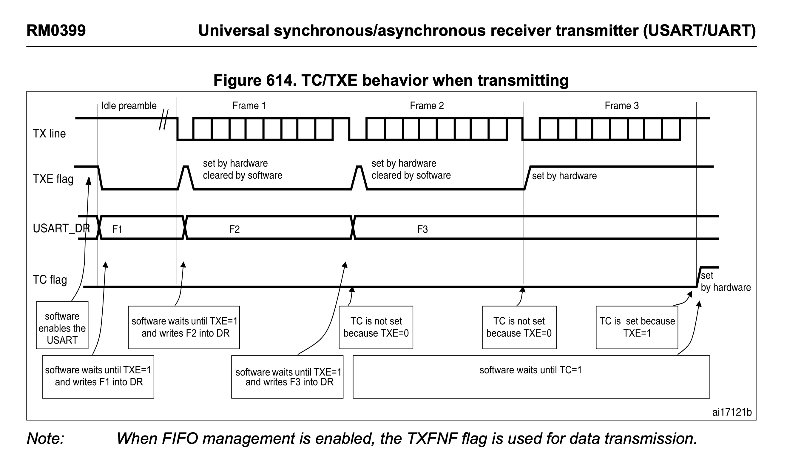
The
TC flag is important, so let's see where this is set. Remember, we are doing a blocking write /// Perform a blocking UART write
pub fn blocking_write(&mut self, buffer: &[u8]) -> Result<(), Error> {
let r = T::regs();
for &b in buffer {
while !sr(r).read().txe() {}
unsafe { tdr(r).write_volatile(b) };
}
Ok(())
}It's only checking the
TXE flag, hmm. Aha... we need to flush! /// Block until transmission complete
pub fn blocking_flush(&mut self) -> Result<(), Error> {
let r = T::regs();
while !sr(r).read().tc() {}
Ok(())
}Finally, this worked
    unwrap!(usart.blocking_write(b"ATB\r\n"));
    unwrap!(usart.blocking_flush());
    debug!("usart_task: Completed blocking write");
USART config in HAL with BufferedUart
Let's first check our setup, and mind you, since starting on this article I've moved to using a BufferedUart so don't be too surprised at the change. One of the downsides of not used a buffered version is that the FIFO buffer has limited capacity, and once it "overflows", well, you loose that data of course. The buffered version, as the name implies, stores that excess (well, yes, it does have a finite capacity) into a buffer in memory (RAM).
This is the default config for the USART peripheral, and has a "bog standard" configuration which is good. Notice the
swap_rx_tx option which is handy if you need to flip your connections in a hurry. We mainly care about the top four entries.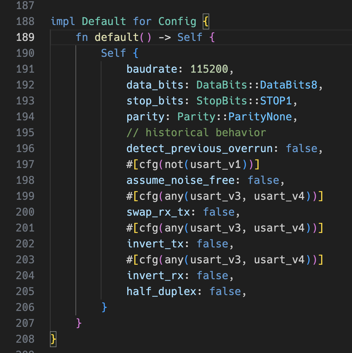
Let's now look at our peripheral config, for my quick test. This isn't production ready by any means, so please bear with me.
The setup here is straight forward, in the sense that we ensure the reader blocks in a separate thread handled by the Embassy executor; all received data is processed by it. We can move our app related logic there and potentially use MPSC (etc) to orchestrate accordingly, but that's for a separate discussion.
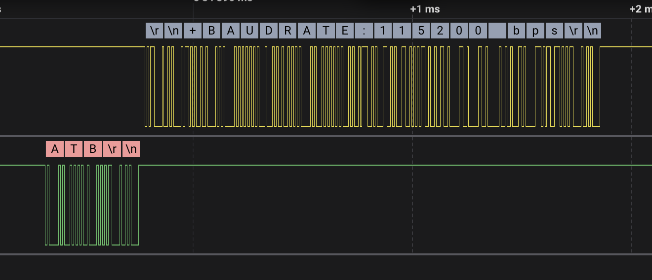
We send our Tx data out at the bottom. For this example, I've now replaced my Uno board with the Sparkfun Dialog ULP WiFi DA16200 R3 Shield which operates via AT commands.
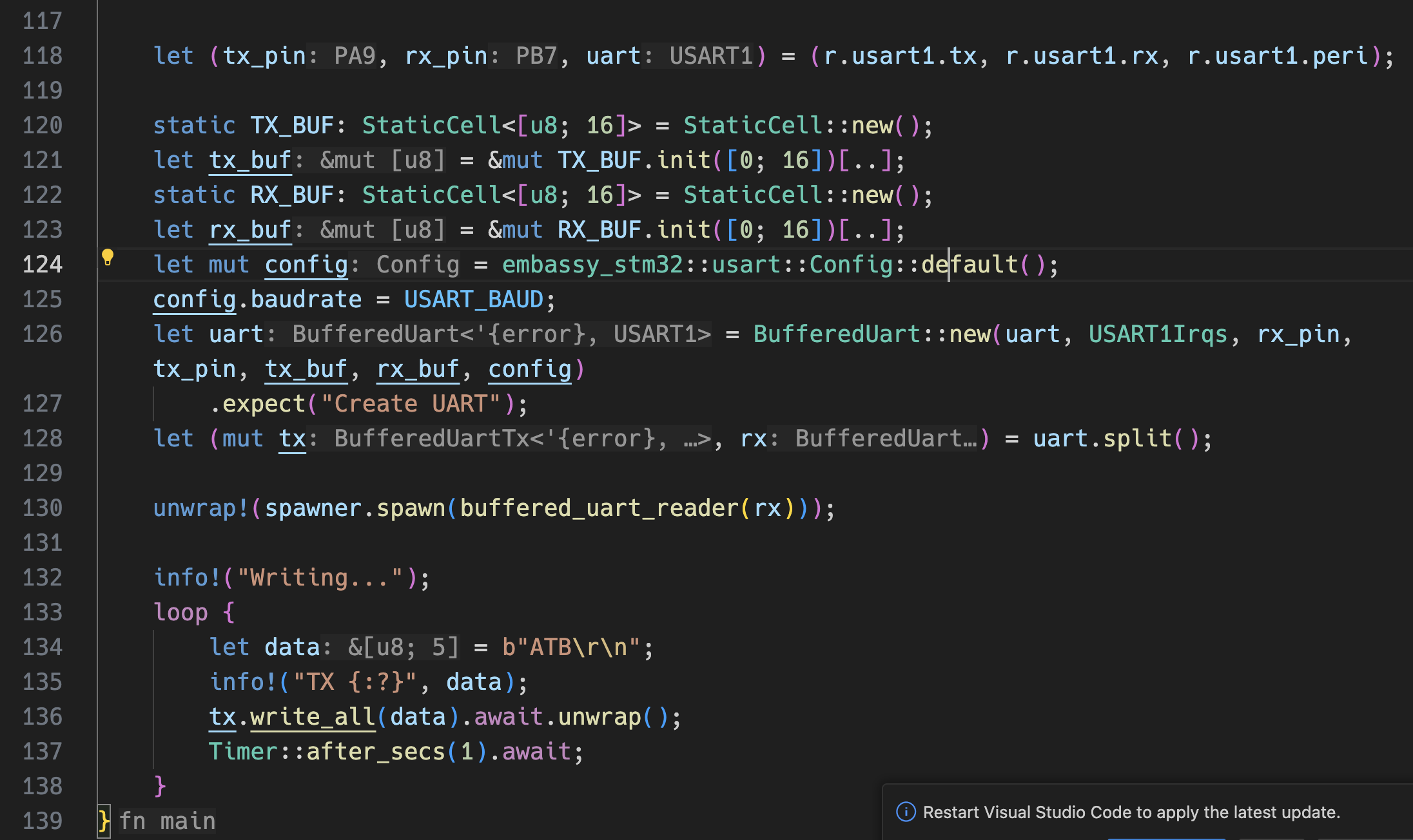
At first I used screen to change the device to 9600baud, but once I got this working I've moved back to 115200baud.
This is where I normally would do a bit of cheering in typical Bill Gates fasion. Yeah, take that your typical high school courty-yard-jock-type bullies! We geeks rule the world now!
I made a minor PR that has also been merged into Embassy. This coming week is going to be a bit involved, but I am planning to get back to this as soon as possible.